Projects01 · Flagship
UAV Quadcopter
Structures lead on a 625 g flight-tested quadcopter, and sole owner of its gimbal from first sketch to flying part.
1 · Challenge
A 625 g maximum mass.
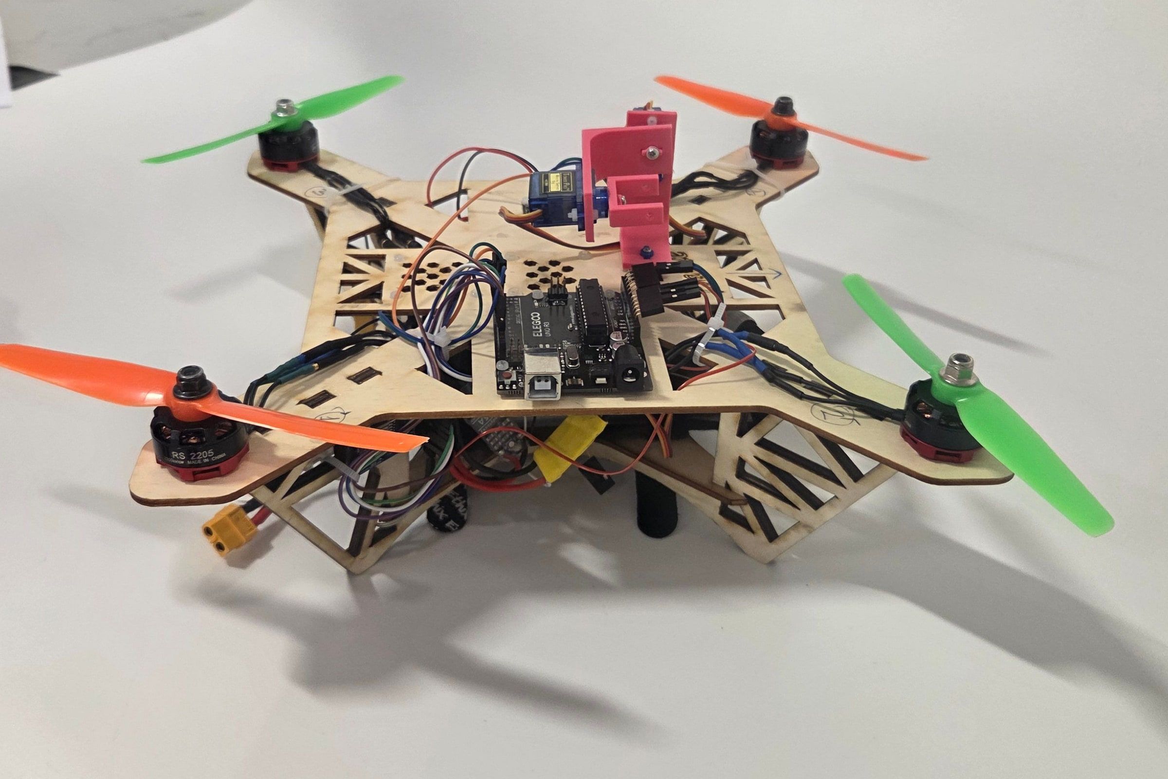
The aim was a lightweight quadcopter carrying a custom three-axis stabilised camera gimbal, with an Arduino on board as a data recorder and a separate flight computer: affordable footage of grassroots outdoor sports (football, surfing, climbing) in under-served areas. The gimbal had to work in pitch, roll and yaw, with a “locked” mode and a “self-levelling” mode switchable remotely, and the drone had to be ready to fly within 5 minutes and hover stably.
Early mass budgeting gave electronics more allowance than it needed, and structures compensated with excess safety margin. Together that pushed the build heavier than planned and exposed a communication gap: as each sub-team’s research moved its plans on, the two halves drifted apart. We fixed it with regular meetings, group discussion and tighter coordination.
2 · What I did
I led the 3-person structures sub-team, coordinating structural decisions and keeping it on track, and contributed to the airframe alongside the others. Most of my own engineering went into the gimbal: I took sole end-to-end ownership of it (CAD, FEA, printing) and was the only team member responsible for all 3D printing.
- With my sub-team, took the airframe through 5 design revisions to optimise weight and manufacturability (laser-cut birch plywood airframe).
- The sub-team ran FEA in SolidWorks Simulation for the 5g hard-landing case and for vibration, iterating the leg design to save up to 35% of structural mass while keeping the safety factor above the 2.5 minimum.
- While I iterated, I gave the avionics team an earlier, near-identical gimbal so they could start integrating.
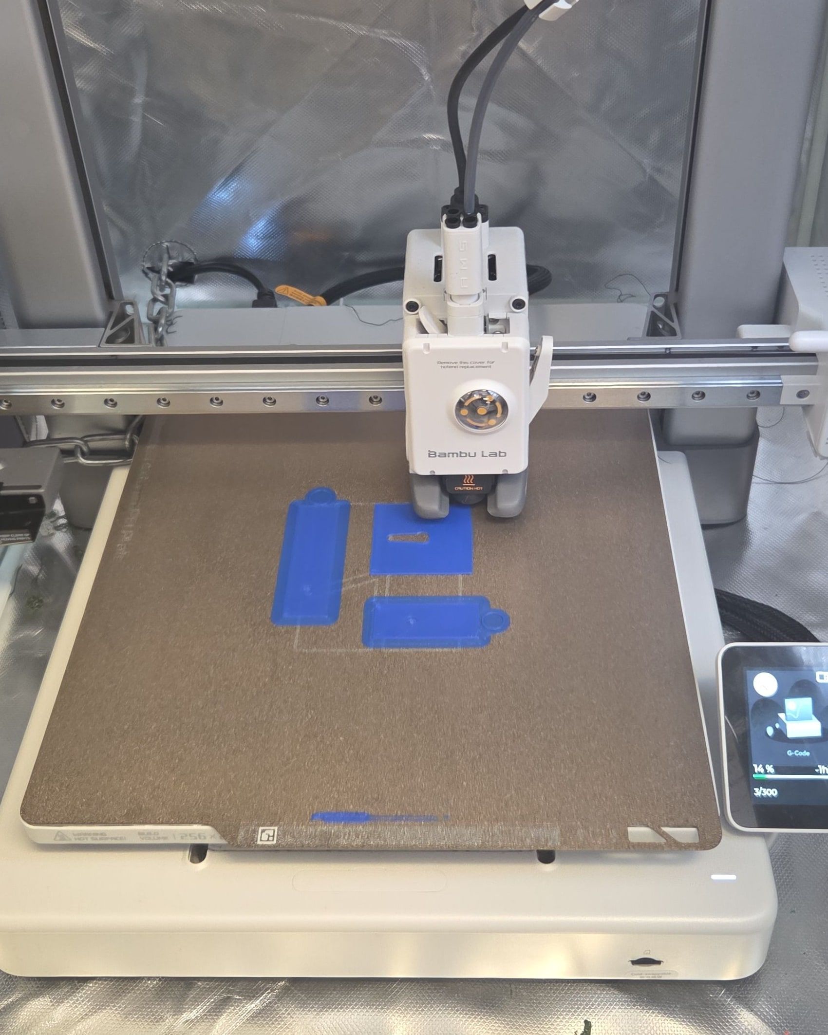
- Managed print settings, material selection and quality checks for every printed part.
2.1 · The gimbal, from first sketch to flying part
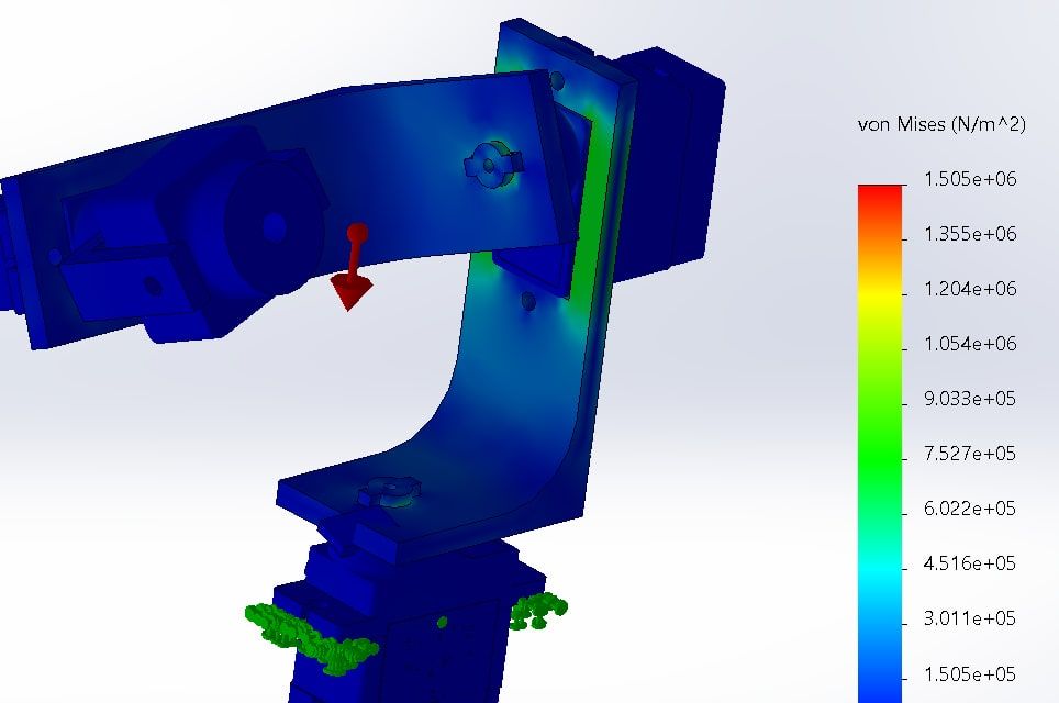
My first version (and my first ever 3D print) was far too big, with no fillets and no real mounting for the camera or motors. I measured the actual hardware, rebuilt it as two arms and a camera mount with aligned holes and fillets, then refined it print by print: adding tolerance where CAD fits perfectly but a printer doesn’t, making room behind the camera for a fastener, and resizing it as the electronics moved so it cleared the Arduino. Mainly PLA (one ABS trial, reverted); a clearance issue took two more redesigns and reprints to fix fastener clearance and vibration isolation in a tight footprint. I chose PLA because it’s cheap and fast to reprint when a tolerance needs adjusting, and the loads are low (the payload’s weight and the correction forces), so its strength is enough. Locking fasteners and thread inserts keep the clamping force under vibration, so movement isn’t lost as slop in the joints. My FEA of the final design put the peak von Mises stress at about 1.5 MPa.
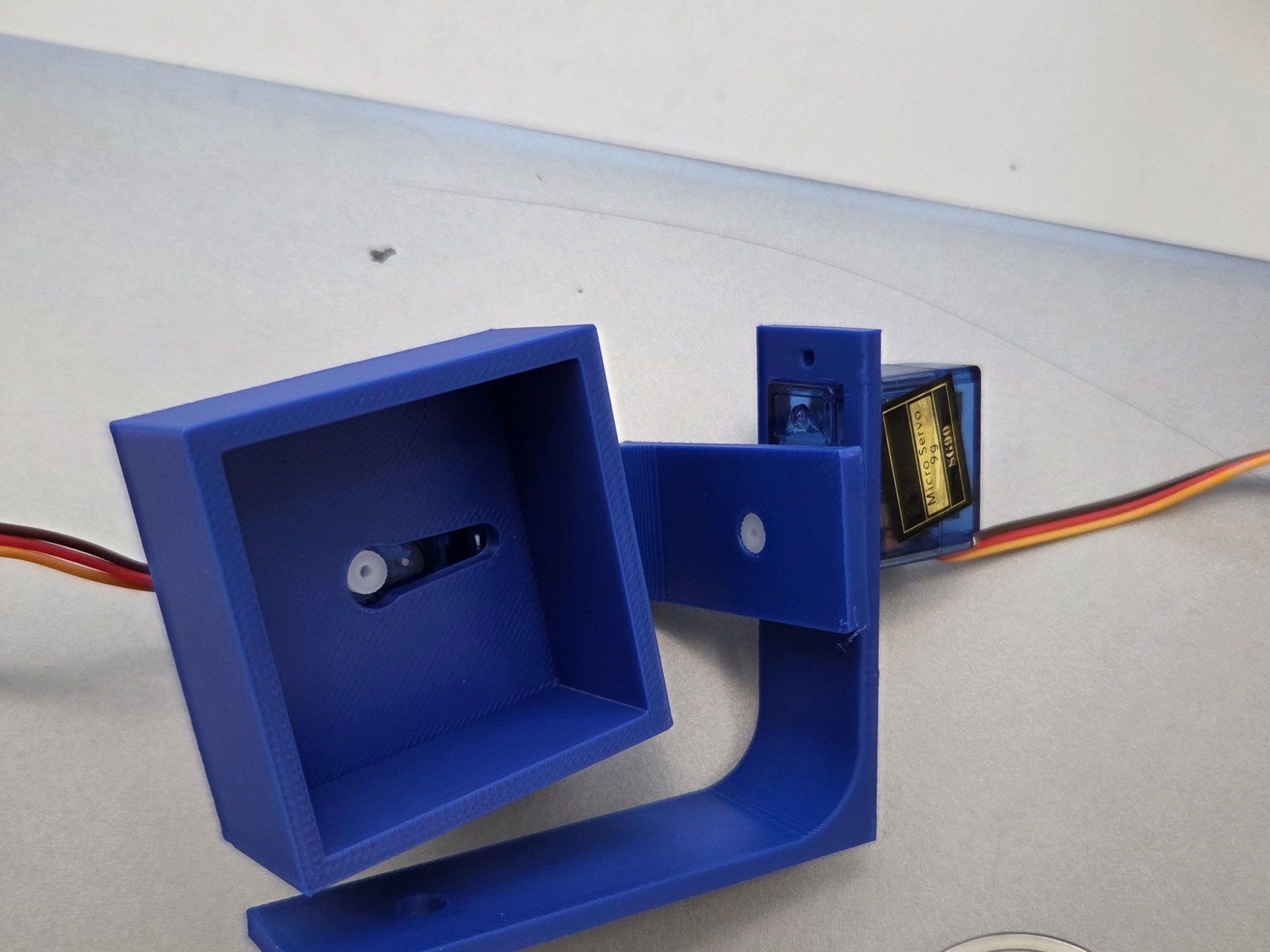
The final design, as drawn for the assembly (yaw arm, pitch arm, camera mount, three locking nuts and three SG90 servos):


2.2 · Airframe and legs
This was team work across the structures sub-team, from Crazy 8s and sketches to quick-and-dirty cardboard prototypes before any CAD, then a weighted design matrix. The final concept combined the lightweight top plate of one design with the X-shaped legs of another.
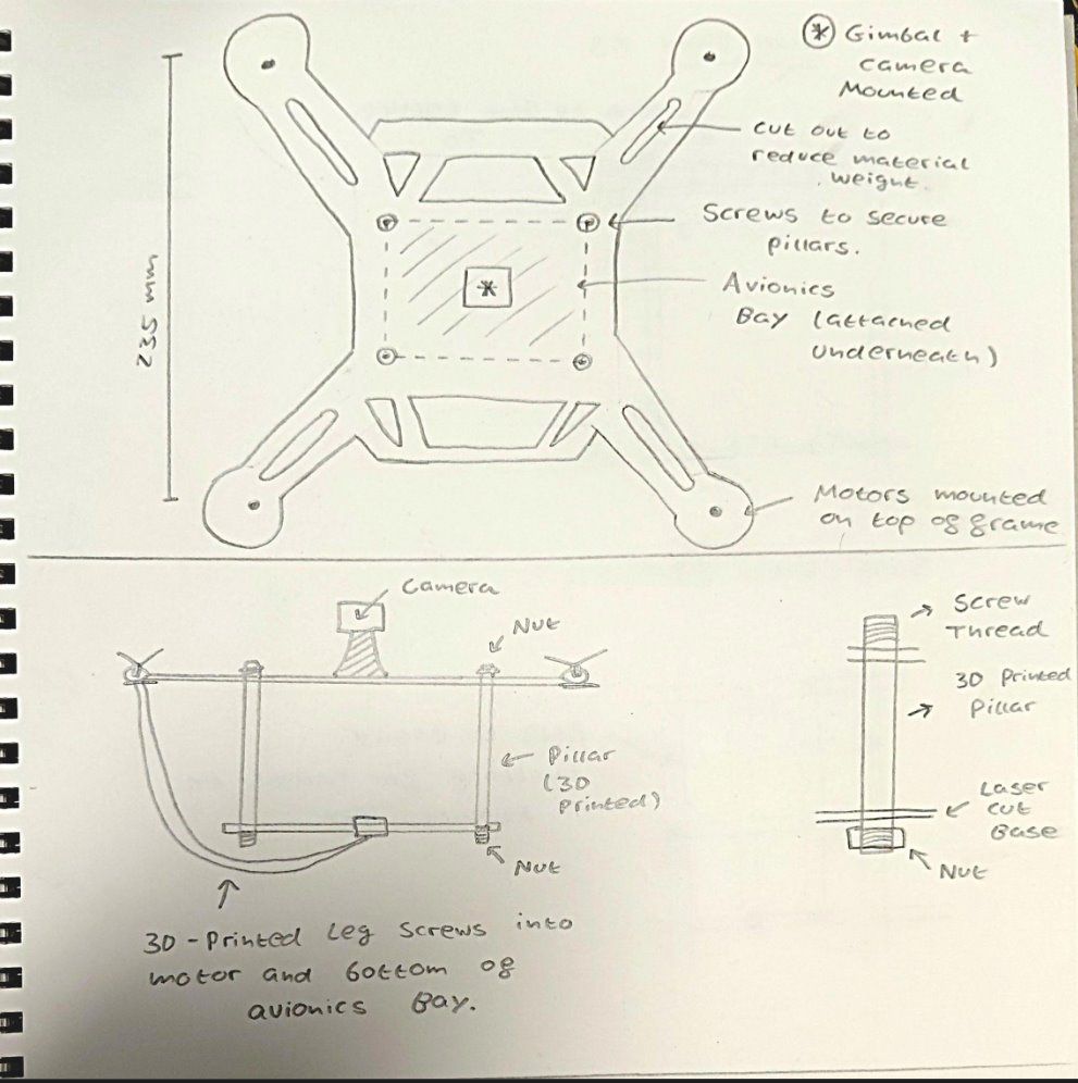
a Concept sketch
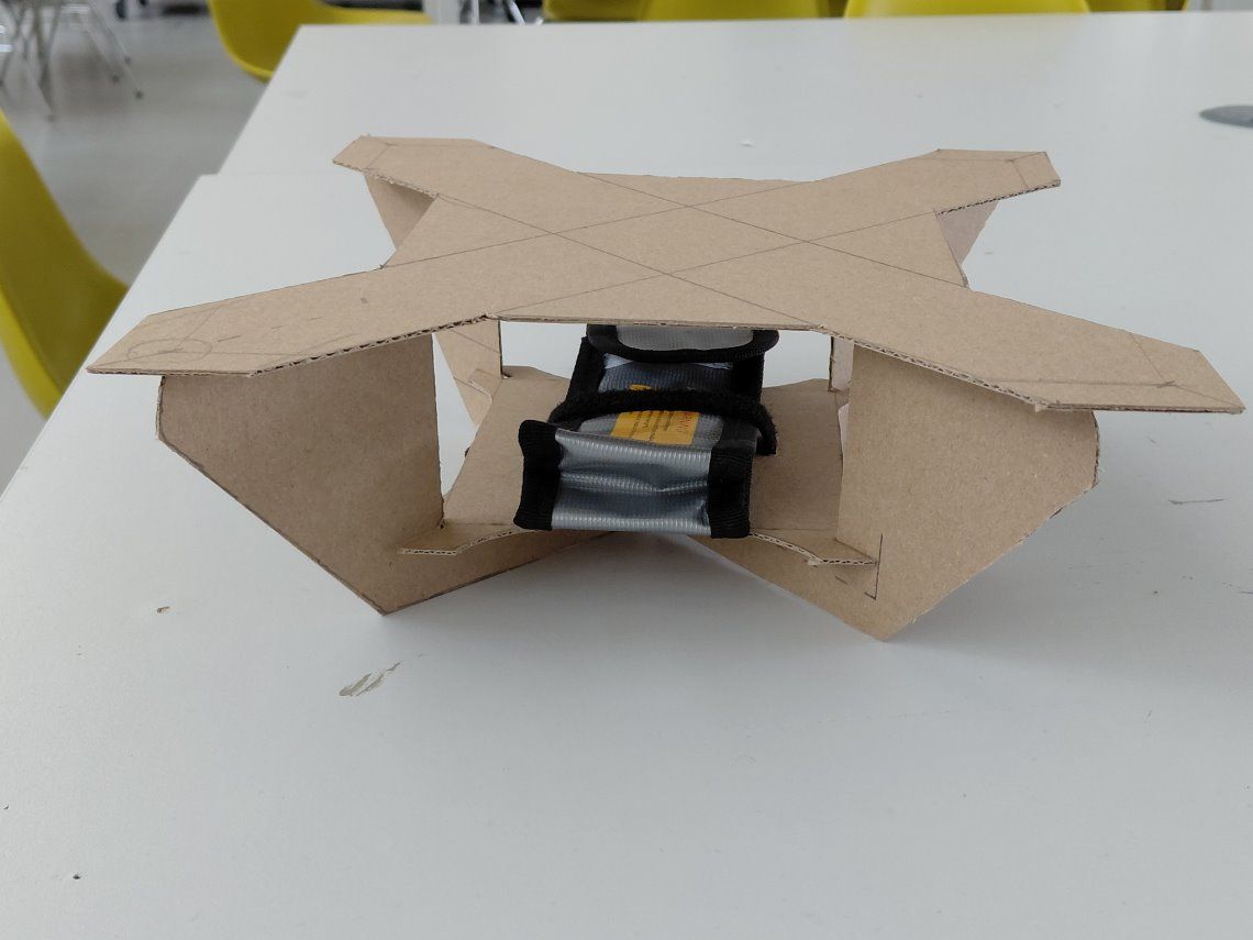
b Cardboard prototype
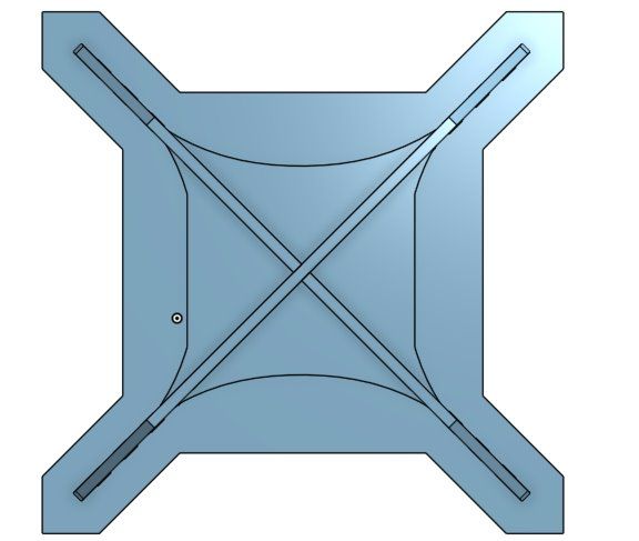
c CAD iteration
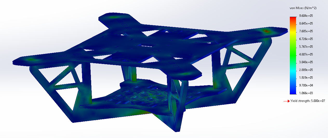
d FEA
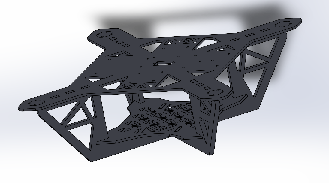
e Final airframe CAD
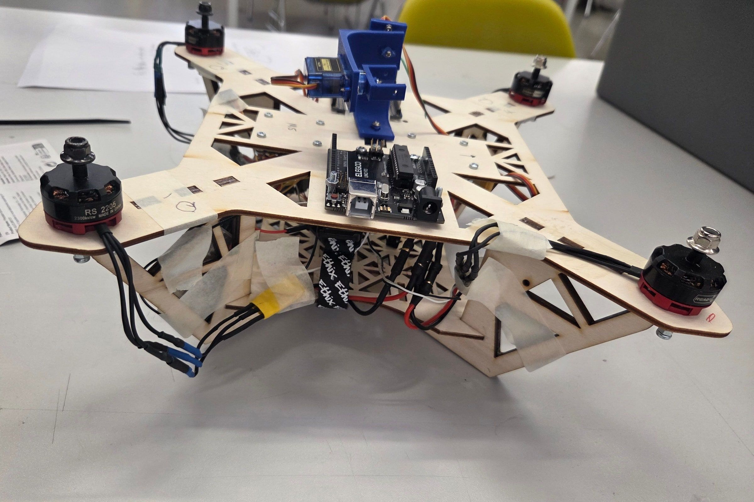
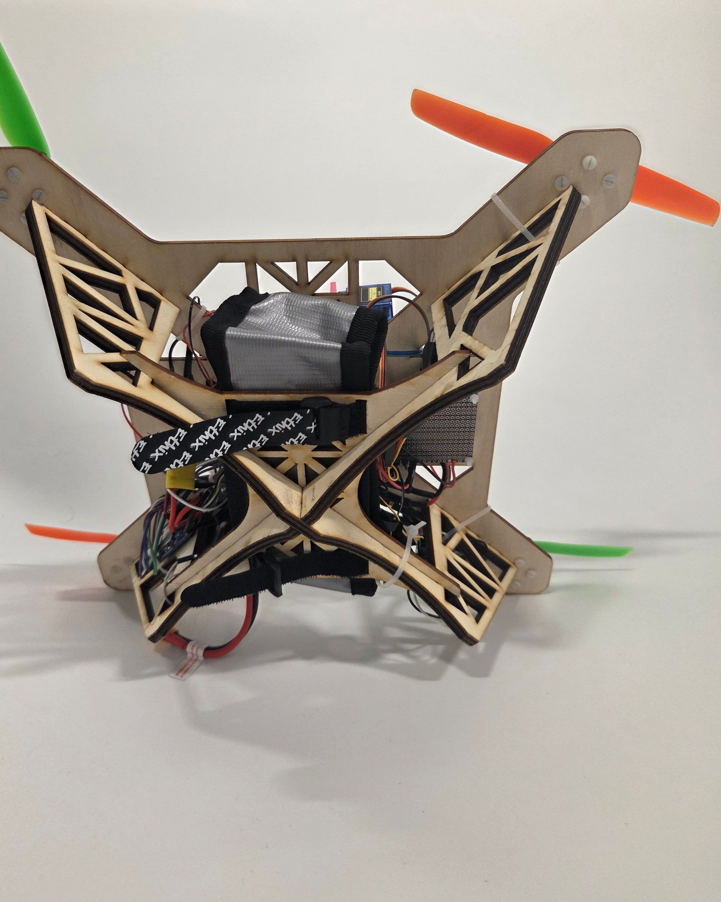
The criteria: plywood yield strength 18 MPa and a minimum safety factor of 2.5, which builds in margin for how uncertain plywood’s properties are. We cut mass from the legs step by step and checked the safety factor at each step:
Cutting the leg height further would have meant redesigning other parts to keep the electronics accessible, so we stopped there.
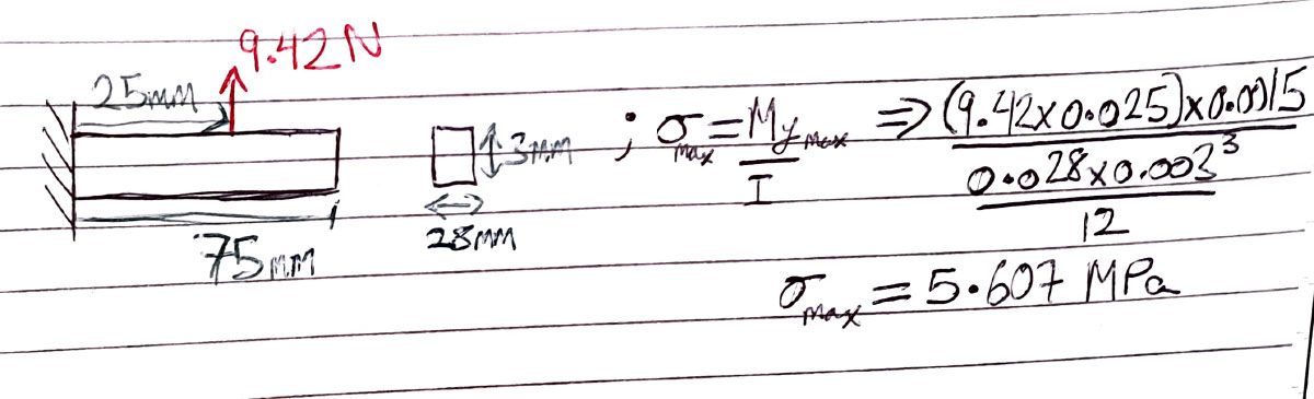
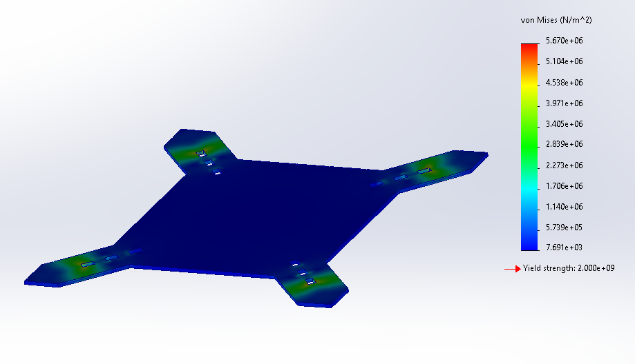
We also checked the FEA by hand. For the top plate under maximum thrust, a hand calculation gave 5.607 MPa against 5.670 MPa from the FEA, about 1.1% apart. A modal analysis showed minimal deformation at resonant frequencies up to about 300 Hz (tested to 600 Hz), against expected excitation of about 100 Hz or less.
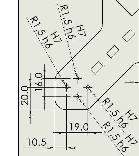
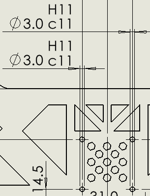
The drawings set the fits: H7/h6 where parts need accurate alignment but must still come apart, H11/c11 clearance for easy assembly (the PDB and soldering board), and ±0.25 mm general tolerance.
3 · Result
The drone flew: it traversed all three axes with stable attitude control, held altitude consistently with minimal drift, and had no structural or wiring failures on the hard-landing case.
On the bench the gimbal compensated manual pitch and roll inputs, a little slowly (a proportional controller). In flight it held the horizon during steady segments, but motor vibration coupling into the IMU caused pitch misreads. That was an avionics/controls limit, not a structural one. Other root causes the team noted: frequent data recording possibly overloading the Arduino (it reset), a slow controller rise time, and stress near the lightweighting cut-outs and connections. At the interim review we gave live demonstrations, including the gimbal responding to controller inputs. Next steps the team set out: a carbon-fibre frame to cut weight, weatherproofing and obstacle avoidance.
Electronics, for context: the Arduino on board mainly logged data to an SD card; a separate flight computer sat under the centre top plate.
4 · What I learnt
Get everyone looking at the same picture early.
Next time I’d push for rough prototypes, like the cardboard mock-ups we built, earlier, and use them to agree the layout across both sub-teams before the detailed work. I’d size from real numbers instead of piling on margin: our airframe ended up one of the sturdiest in the cohort, which made late weight cuts easy, but that weight should never have been there. And I’d get the gimbal flying sooner, for more testing time with the controller.