Projects02
SAR UAV: Wing Design & Structural Analysis
Designed and validated the wing for a Snowdonia search-and-rescue UAV, from aerofoil selection to a 1:5 scale model, with no prior tool experience.
1 · Context
5-person team designing a fixed-wing UAV for Snowdonia mountain search and rescue. Brief: a 36-unit fleet, LiDAR + high-res camera + FPV, under 10 kg, high-altitude long-endurance flight over mountainous terrain. The team chose its concept with a weighted decision matrix (aerodynamic efficiency, high aspect ratio, stability, ease of manufacture): Concept 4 scored 33, against 29, 28 and 22, with front and rear contra-rotating propellers, FPV, LiDAR and thermal cameras, and long slender wings. My part was wing design and structural analysis.
2 · What I did
- Tested 11 NACA aerofoils in XFLR5 at Re = 150,000 (calculated for cruise at 1 km altitude over Snowdonia) and selected NACA 4312 for the highest Cl_max.
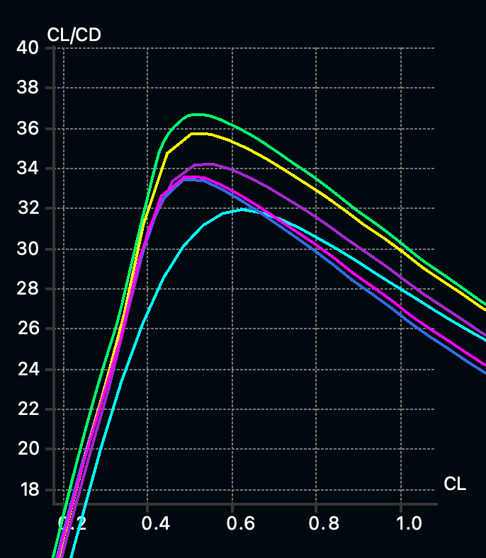
- Designed 15 wing planform iterations to raise Cl/Cd at cruise. The elliptical Design 1 had the lowest, 26.7, and I explored root dihedral for stability. Sweep came out of my XFLR5 testing, new versus the group design.
- Wrote a custom Python script (trapezoidal rule) for bending moment, slope and deflection along the span.
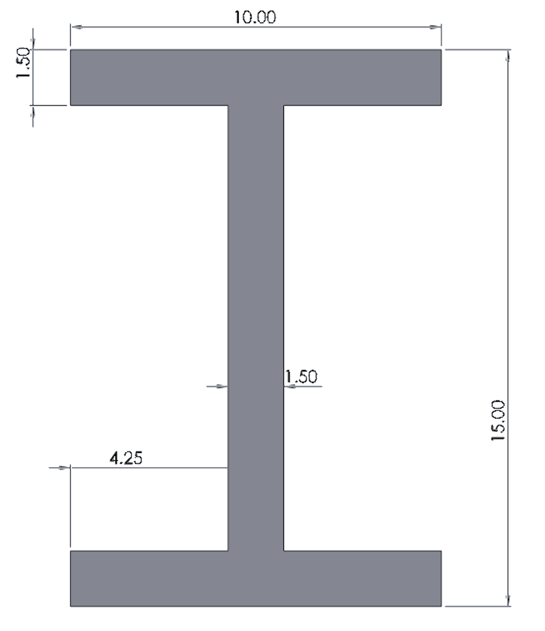
- Compared Aluminium 7075-T6 (E = 71.1 GPa) against Carbon Fibre M60J (E = 588 GPa), chose M60J, and designed an I-beam spar cross-section.
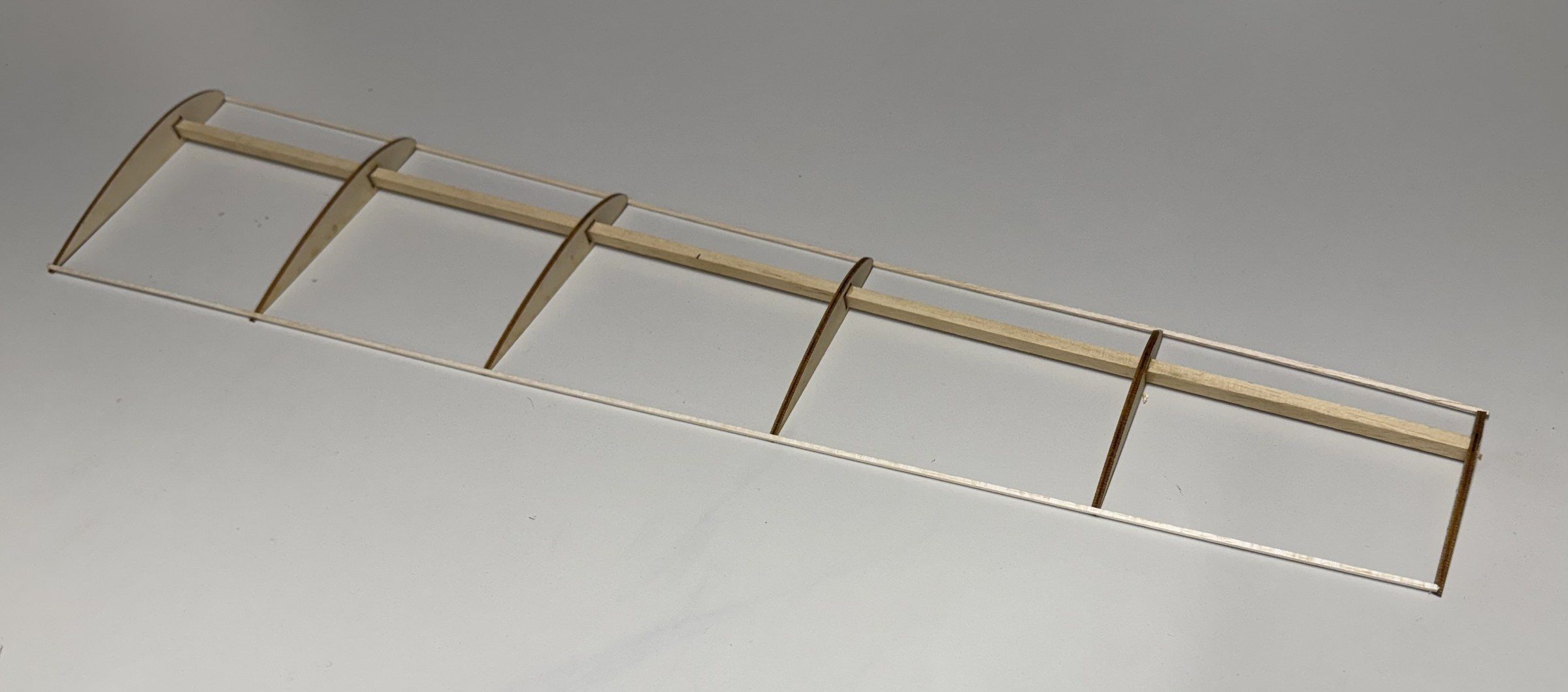
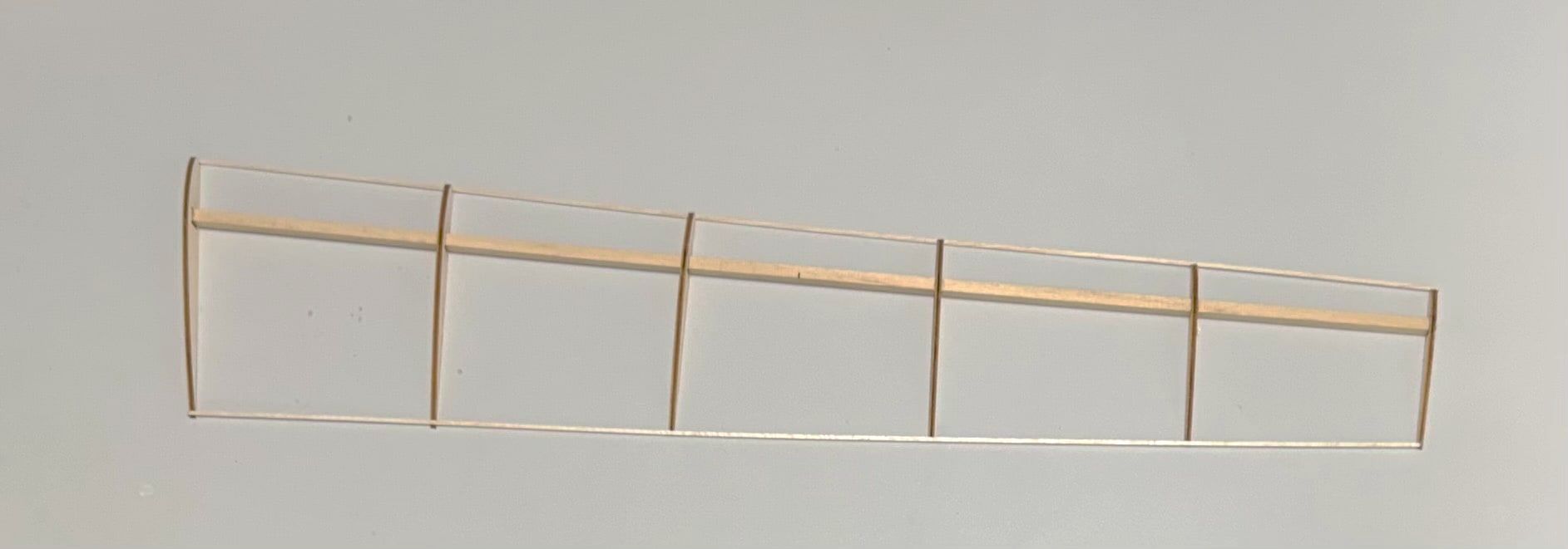
- Built a 1:5 scale physical model. The wing tapered so sharply that the tip parts were too small for the laser cutter and kept breaking, so I doubled the model’s scale to make it buildable. Seeing the real tip come out far smaller than it looked in CAD taught me more than the simulation did.
- Max camber
- 4% c at x/c = 0.3
- Max thickness
- 12% c at x/c ≈ 0.30
- Solid line
- chord, LE to TE
- Dashed line
- mean camber line
2.1 · The final wing
- Span
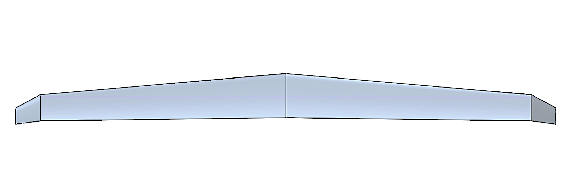
- 3.3 m
- Root / tip chord
- 0.27 m / 0.16 m
- Aspect ratio
- 15.9
- Taper ratio
- 0.37
- Root-to-tip sweep
- 5.8°
- Winglet dihedral
- 40°
- Aerofoil
- NACA 4312
- Spar
- Carbon fibre M60J, I-beam
2.2 · The 1:5 model
The model has 6 ribs laser-cut from 3 mm plywood on a 3 mm square wooden spar, because a scaled I-beam was too small to make. I cut the rib holes 0.2 mm wider than tall so the spar could sit at an angle. It shows spar position and rib spacing like an x-ray view.
3 · Result
A fully justified wing design with documented structural analysis and a physical model, done end to end in first year.